
Keeping the Power Where It Belongs: Semiconductor Heater Wiring
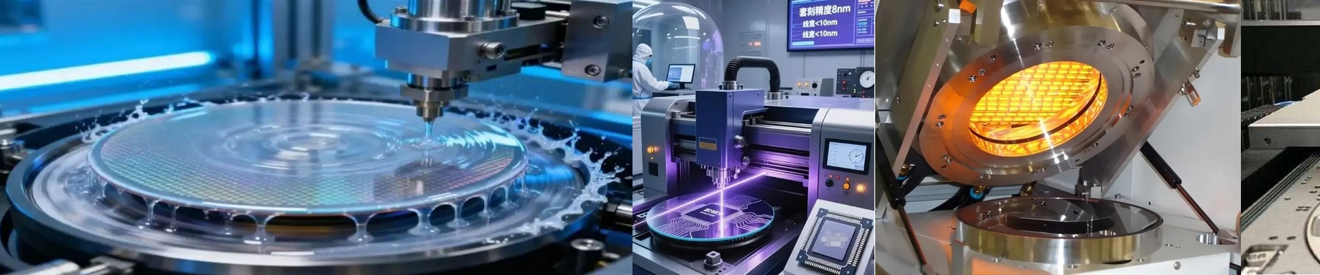
In semiconductor manufacturing, electrical leakage is a nightmare. There’s just no room for it. That’s why we stick with Teflon (PTFE) coated wiring for our heater assemblies. It handles the heat without melting or releasing those nasty gases that can ruin a cleanroom. But honestly? The material is only half the battle. Every single wire that leaves our shop goes through a full voltage withstand and insulation resistance test. No exceptions. Why we don’t do “spot checks” Here’s the thing: a tiny pinhole leak in the insulation can send a short straight to the chassis. That doesn’t just trip a breaker. It kills your entire wafer batch. To stop that from happening, we push the wiring right to its rated voltage limit. We want to see if the dielectric strength actually holds up. If a wire fails the hipot test, it goes in the scrap bin. Period. We don’t just test a few samples and hope for the best. The reality of using PTFE Teflon is the gold standard here because it stays stable while PVC or silicone would just burn up. It’s slick, it resists chemicals, and the walls are thin, which keeps the whole footprint small. But there is a trade-off. PTFE is stiffer than silicone. If your heater design involves tight, repeated bending, you’ve got to be careful with your bend radius. Push it too far and you’ll stress the conductor. Getting it into your system When you plug these into your gear, that insulation resistance is what keeps the current inside the heating element. It stops that annoying parasitic leakage that messes with your sensitive sensor readings. We test for dielectric breakdown because we know these wires take a beating from thermal cycling. They expand, they contract, and they get hot. We make sure they won’t crack under pressure. And a quick tip: make sure your power supply is actually spec’d for the leakage current of your heater array. If it isn’t, you’re going to deal with a lot of nuisance trips, and nobody wants that.